 by
by Introduction
Secure boot allows an STM32U5 microcontroller to check whether an application can be trusted before executing it. The device combines the Arm Cortex-M33 processor and Armv8-M TrustZone with STM32 security controllers, protected storage and hardware cryptographic accelerators.In this post, we will discuss the basics of these security mechanisms in the simplest terms possible.
The STM32U5A5 uses a Cortex-M33 implementing the Armv8-M architecture. Compared with Armv7-M devices, it provides stronger hardware support for secure boot:
- TrustZone: Separates memory, peripherals and execution into Secure and Non-secure worlds.
- Protected root of trust: The bootloader, cryptographic keys and verification code can remain inaccessible to the Non-secure application.
- Controlled transitions: Non-secure code can call Secure services only through defined Secure Gateway entry points.
- Hardware-enforced memory attribution: The SAU and STM32 security controllers determine which flash, RAM and peripherals are Secure.
The device can divide flash, RAM and peripherals into Secure and Non-secure regions. For example, the bootloader and cryptographic keys can be stored in Secure flash, while the main application runs from Non-secure flash. The Security Attribution Unit (SAU) and STM32 security controllers enforce these boundaries in hardware, so Non-secure code cannot directly read, modify or execute protected memory, even if it contains a software bug or has been compromised. - STM32U5 protections: STM32U5A5 protections include hardware cryptography, secure data storage using a hardware unique key, flash write protection, hide-protection areas, debug protection and secure firmware-update support. You can read more about these features in the STM32U5A5 datasheet.
How Hardware memory protection works?
Suppose 0x20000000 has been configured as Secure RAM by the Security Attribution Unit (SAU) and STM32 security controllers. Now consider the following piece of code:
Example: A Non-secure access to Secure RAM
// non_secure_access.cpp <cstdint>int main(){ constexpr std::uintptr_t secure_address{0x20000000U}; auto* secure_data = reinterpret_cast<volatile std::uint32_t*>(secure_address); const std::uint32_t value{*secure_data}; // Hardware blocks // this access. (void)value; for (;;) { }}
The C++ compiler accepts the pointer access because it does not know the runtime security configuration. When the Cortex-M33 executes the load instruction in Non-secure state, the SAU and IDAU (Implementation-Defined Attribution Unit) identify the address as Secure. The processor blocks the access and raises a SecureFault instead of returning the protected data.
The address 0x20000000 is used only as an example. Whether it identifies Secure or Non-secure memory depends on how the Security Attribution Unit (SAU) and the STM32 security controllers have been configured.
So if we have a function like this in the code:
// non_secure_access.cpp#include <cstdint>std::uint32_t read_memory(std::uintptr_t address){ auto* data = reinterpret_cast<volatile std::uint32_t*>(address); return *data;}
If Non-secure code calls read_memory() with an address that the SAU or IDAU classifies as Secure, the Cortex-M33 blocks the access and takes a SecureFault exception. The AUVIOL bit in the Secure Fault Status Register indicates an attribution-unit violation.
Two Layers of Hardware Level Securtiy
An access must pass both the Cortex-M33 security check and the STM32 security-controller check.
- Suppose, the Cortex-M33’s Security Attribution Unit (SAU) classifies an address that the application is trying to access an Non-secure address, the processor will the access.
- However, it may so happen that the STM32-specific security controller, such as the Global TrustZone Controller (GTZC), still may classify the memory address as Secure.
In this scenario the following may happen:
- A read may return zero.
- A write may be ignored.
- A bus error or illegal-access event may be generated.
You can refer to the Arm Cortex-M33 documentation to know more about ST’s STM32U5 TrustZone access rules.
Option bytes
Even before the TrustZone gets activated there are ways to protect the invalid access via the Option Bytes. Option bytes are non-volatile configuration settings that the STM32U5 reads during reset, before running the Secure bootloader or application. They remain stored in the flash and determine how the microcontroller boots and which initial security restrictions are enforced. For example, option bytes can:
- Enable TrustZone.
- Select the Secure and Non-secure boot addresses.
- Protect selected flash regions against reading or modification.
- Control permitted boot sources and debug access.
Option bytes can be configured using STM32CubeProgrammer. They must be changed carefully because an incorrect boot address can prevent the application from starting. Readout Protection Level 2 is irreversible, so the device cannot subsequently return to a lower readout-protection level.
Root of Trust
The Root of Trust is the protected starting point of the boot process. On the STM32U5A5, option bytes enables TrustZone and force execution to begin at a configured Secure boot address. This is typically the bootloader base address defined in the linker script.
Chain of Trust
On reset, the processor reads the option bytes. These specify settings such as whether TrustZone is enabled, the readout-protection level and the Secure boot address. The processor then starts executing the Secure bootloader from that address.
The Secure bootloader configures the Security Attribution Unit (SAU) and the STM32 security controllers. It calculates a cryptographic hash of the application image and verifies the image’s digital signature using the trusted public key. The public key can be compiled into the bootloader and stored with it in protected Secure flash, such as a configured Hide Protection Area (HDP).
The corresponding private key remains outside the STM32, normally in a Hardware Security Module (HSM) used by the firmware-signing system. The private key signs the application before it is distributed and is never transferred to the microcontroller.
If signature verification succeeds, the bootloader transfers control to the application linked at the application base address defined in its linker script. If verification fails, the bootloader does not start the application.
Image Verification
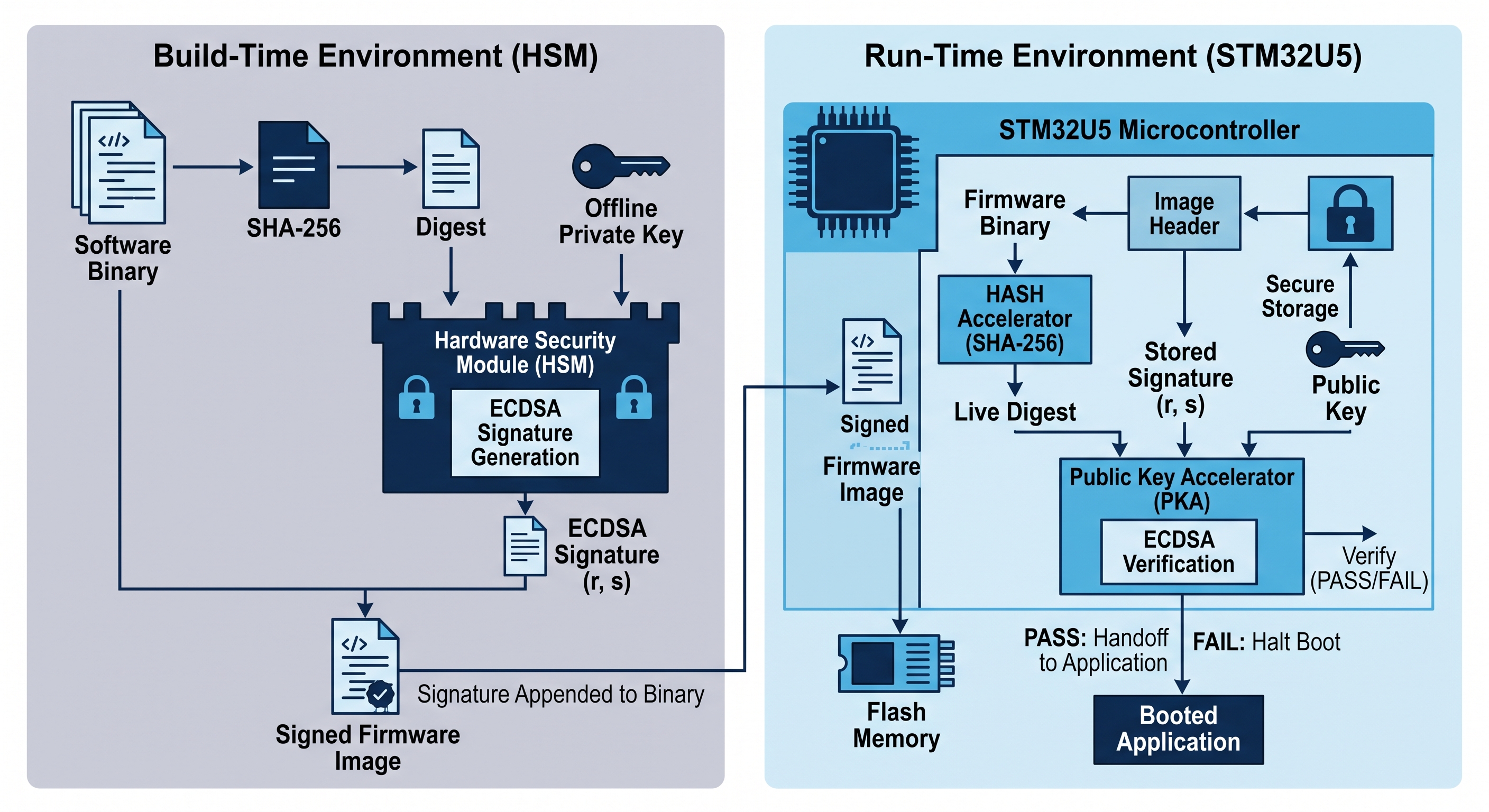
The image verification architecture in the STM32U5 relies on asymmetric cryptography (ECDSA), where the microcontroller performs verification using an internal public key. The private key remains strictly isolated inside a Hardware Security Module (HSM). The following are the typical steps that are involved in an image verification process:
Preparing and checking the application image
The following sequence shows a typical STM32U5 secure-boot process. Image signing is required for authenticity, while image encryption is optional.
1. Create the keys
An ECDSA public-private key pair needs to be generated. There are two way you can generate the keys:
1. ST Provides Tools to Generate Keys STMicroelectronics provides software utilities within their ecosystem to generate ECDSA public-private key pairs directly on a host machine:
- STM32 Trusted Package Creator (integrated into STM32CubeProgrammer) includes commands to generate keys, sign firmware, and output public key files (like
.pemor raw binary bytes) as well as Option Bytes Keys (.obk). - STM32 KeyGen CLI is a standalone utility provided by ST specifically to generate ECC/ECDSA key pairs and formatted hashes for secure boot configurations.
Using these tools, developers can generate key pairs locally on a workstation during early prototyping, board bring-up, or testing.
2. Production Key Generation (The HSM Requirement) While ST software tools can generate keys, generating software keys on a general-purpose developer PC exposes the private key to local disk storage, RAM dumps, or malware.
For commercial products and mass manufacturing:
- The recommended industry best practice is to generate the ECDSA key pair inside an HSM (or use a dedicated hardware security environment like an ST smartcard HSM module).
- The private key is generated directly on the HSM’s silicon and marked as non-exportable.
- Only the corresponding public key is exported from the HSM so ST tools (or the programmer) can load it into the STM32’s Option Bytes Keys (OBK), OTP, or secure Flash.
ST’s tools (like STM32 Trusted Package Creator) support direct hardware integration with HSM modules via PKCS#11 interfaces, allowing the software tools to send image digests to the HSM for signing without ever needing or seeing the raw private key.
2. Store the trusted key information
The public key, or its SHA-256 hash, is programmed into One-Time Programmable (OTP) memory area in the flash.
If only the public-key hash is stored in OTP, the complete public key is stored in protected Flash or included with the image. The bootloader checks that key against the trusted hash before using it.
3. Sign the application
The build system calculates a SHA-256 hash over the application and the metadata. This hash is passed to the HSM. The HSM uses the private key to sign that hash and returns the ECDSA digital signature (r, s). The build tool adds the signature to the image file.
4. Encrypt the application if required
Encryption is optional and prevents someone from reading the firmware. The application is normally encrypted using a symmetric algorithm such as AES. The AES encryption key is separate from the ECDSA signing keys and must be securely available to the STM32.
5. Decrypt the application
If encryption is enabled, the secure bootloader obtains the protected AES key and decrypts the application during installation or before execution, depending on the update design. This step is skipped when the image is not encrypted.
6. Check the public key
If OTP contains the public-key hash, the bootloader reads the complete public key from the image header, calculates its SHA-256 hash, and compares the result with the trusted hash stored in OTP. If they do not match, the bootloader rejects the image.
7. Verify the application
The bootloader calculates the hash of the application image and extracts the digital signature and public key from the image header. The bootloader passes the following to the to the ECDSA verification process:
- calculated application image hash
- digital signature
- and public key.
ECDSA checks mathematically whether the signature is valid for the calculated hash and public key. If the image changes, its hash changes and signature verification fails.
8. Start the application
If verification succeeds, the bootloader reads the initial stack pointer and reset-handler address from the application vector table and starts the application. If verification fails, the bootloader rejects the image and follows its configured failure or recovery process.
For detailed hardware specifications on how STMicroelectronics implements Root Security Services and hardware-level boot execution on Cortex-M33 architectures, see this video:
Live STM32 project
Put STM32 secure boot into practice
If you would like hands-on experience bringing up an STM32 system and implementing secure boot, firmware signing and image authentication, join me in the live project.
Discover more from Tech For Talk
Subscribe to get the latest posts sent to your email.
Leave a Reply