 by
by Introduction
In an increasingly interconnected world, the ability to gather and process data from the environment is quite critical. This post demonstrates the journey of building a sophisticated cloud-connected sensor node using the STMicroelectronics B-U585I-IOT02A Discovery Kit. This project combines the power of a custom bootloader written in C with robust application firmware developed in Rust, offering a unique approach to sensor data acquisition, wireless communication, and cloud integration.
Through this initiative, we aim to demonstrate the seamless transition from microcontroller startup to the publishing of telemetry data on AWS IoT Core. Leveraging the capabilities of the STM32U585AI microcontroller, with its integrated sensors for temperature, humidity, motion, and more, we will dive into the intricate processes of data collection, JSON telemetry formation, and MQTT interactions.
With a focus on creating a simplified yet effective sensor-to-cloud solution, this post will cover each phase of the project, from hardware setup and software architecture to cloud processing and visualization. Join us as we explore the complete engineering pathway that transforms raw sensor measurements into actionable insights, showcasing the power of modern IoT technology.
What You Will Learn
Build a working STM32 home-monitoring system, then extend it into a complete device-to-cloud solution using MQTT and AWS.
STM32 Home Monitoring
- Set up the STM32 development environment
Install and configure STM32CubeMX, STM32CubeIDE and STM32CubeProgrammer.
- Configure the STM32 project
Create the project, manage its .ioc configuration and prepare the board for development.
- Integrate the ten onboard sensors
Understand how the sensors connect to the STM32U5 and integrate their drivers.
- Capture sensor measurements
Read and organise measurements from the connected sensors at regular intervals.
- Display live readings on the console
Format and print the captured sensor data for verification and debugging.
AWS Cloud and IoT
- Set up the AWS environment
Create an AWS account and learn the cloud fundamentals required by this project.
- Connect the device using MQTT
Configure the IoT connection and publish sensor measurements to the remote MQTT service.
- Receive and route IoT data
Receive MQTT messages in AWS and route them through the AWS IoT Rules Engine.
- Process and store sensor data
Use AWS Lambda for processing and configure DynamoDB for persistent storage.
- Create the monitoring dashboard
Present the processed sensor readings and project results through a cloud dashboard.
A working STM32 sensor-acquisition system with an optional end-to-end AWS pipeline for MQTT ingestion, data processing, storage and dashboard visualisation.
Mode of Delivery
The programme is delivered through a practical, guided implementation of the complete project.
- A minimum of ten live, one-to-one online training sessions
- Step-by-step instructions for executing the complete project within your own development environment
- Guidance to identify and resolve issues encountered while building, testing and debugging the project
- Complete project source code
Contact Me
Interested in joining the programme or learning more about the project? Send us a message.
For more details, book a one-to-one session with me for an introduction to the project.
Book an Introductory SessionProject Objective
The objective of this live project is to build a complete cloud-connected sensor node using the STMicroelectronics B-U585I-IOT02A Discovery Kit.
The system will combine a custom bootloader developed in C with application firmware written in Rust. The Rust application will acquire environmental and motion data from the onboard sensors, structure the readings as JSON telemetry, connect to a wireless network and publish the telemetry using MQTT to AWS IoT Core.
On the cloud side, an AWS IoT rule will process selected fields from the incoming messages and route them to a storage or logging service. A basic dashboard will then display the latest sensor readings and their changes over time.
The purpose is to demonstrate the complete engineering path from microcontroller start-up and firmware handover through sensor acquisition, wireless communication, cloud processing and visualisation.
Hardware Platform
The project uses the B-U585I-IOT02A Discovery Kit, which is based on the STM32U585AI microcontroller.


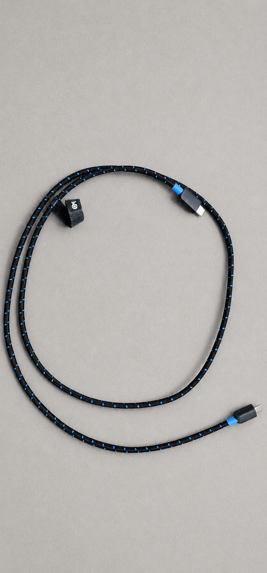
The STM32U585AI provides:
- An Arm Cortex-M33 processor
- 2 MB of internal Flash memory
- 786 KB of SRAM
- Integrated security capabilities
- Low-power operating modes
- Multiple communication peripherals
The Discovery Kit includes Wi-Fi and Bluetooth connectivity together with several onboard sensing devices, including:
- Temperature and humidity sensing
- Atmospheric pressure sensing
- Accelerometer and gyroscope
- Magnetometer
- Time-of-Flight sensing
- Gesture detection
- Digital microphones
These integrated components make the board suitable for developing a complete sensor-to-cloud application without requiring several external expansion boards.
More information about the hardware is available from the official B-U585I-IOT02A product page.
Overall System Architecture
Architecture Diagrams

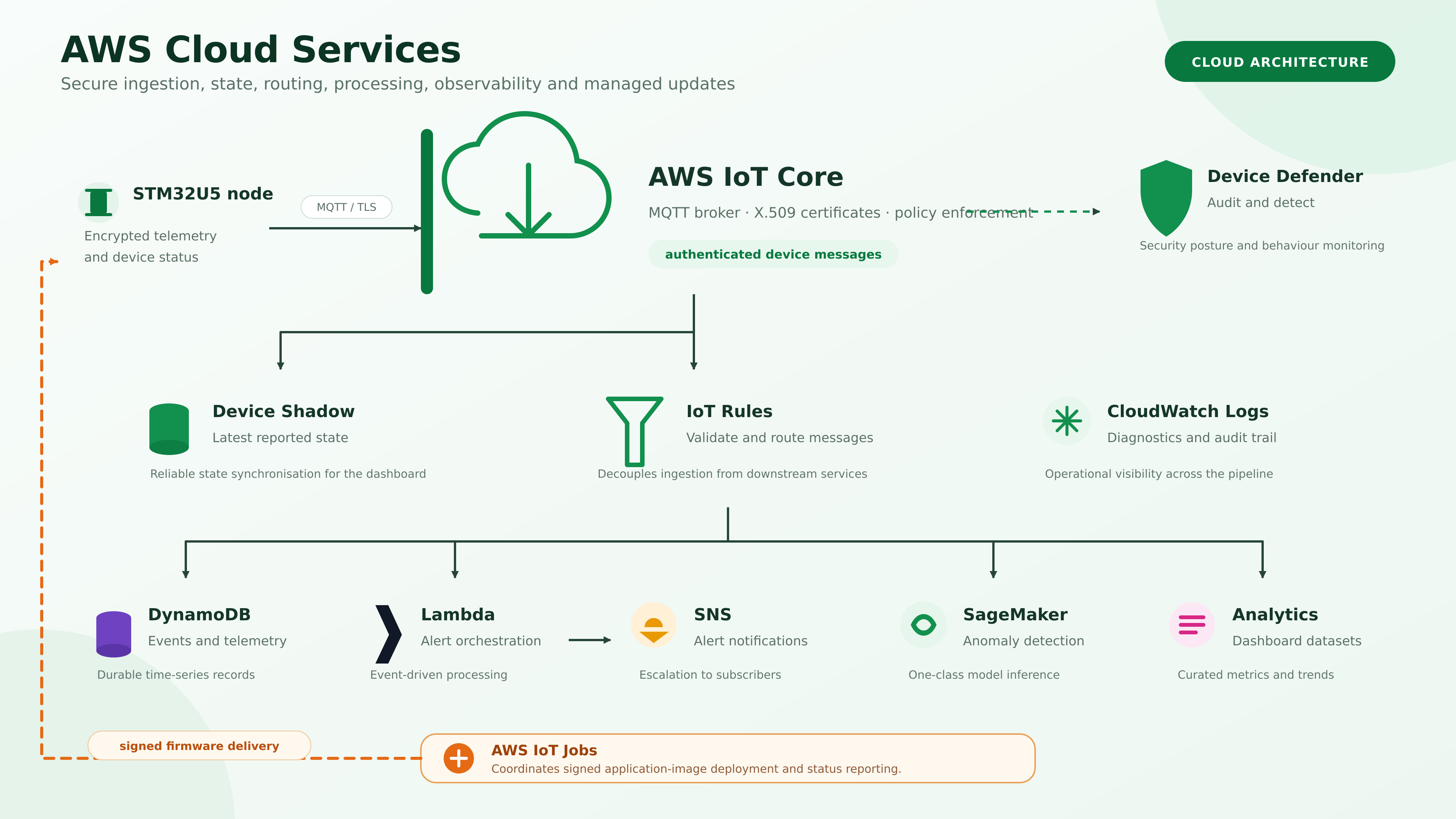


The project is divided into six principal layers.
1. C Bootloader
A custom bootloader developed in C will execute immediately after the microcontroller resets. The bootloader is located at the beginning of the STM32 internal Flash memory at: 0x08000000
Its initial responsibilities will be to:
- Perform the required microcontroller initialisation
- Locate the application image
- Validate the application vector table
- Check the initial stack pointer and reset-handler address
- Prepare the processor for the application handover
- Set the application vector-table address
- Load the application stack pointer
- Transfer execution to the Rust application
The application firmware is configured to start at: 0x08040000
The initial implementation will provide controlled bootloader-to-application handover. Cryptographic signature verification and secure firmware updates are outside the first project scope.
2. Rust Application Firmware
The main application firmware will be written in Rust and compiled for the STM32U585 Arm Cortex-M33 target.
The Rust application will be responsible for:
- Initialising the required hardware peripherals
- Managing application timing and execution
- Communicating with the onboard sensors
- Processing and validating sensor readings
- Constructing JSON telemetry messages
- Managing Wi-Fi and MQTT communication
- Detecting connection failures
- Attempting reconnection after short interruptions
- Providing diagnostic information during development
Keeping the bootloader and application as separate projects creates a clear firmware boundary. The C bootloader controls the start-up and handover process, while the Rust application contains the sensor-node functionality.
3. Onboard Sensor Acquisition
The Rust firmware will acquire values from at least three onboard sensors.
The initial sensor set is expected to include:
- Temperature
- Relative humidity
- Atmospheric pressure
- Motion or acceleration
The selected sensor drivers will initialise each device, collect readings and convert the raw values into suitable engineering units.
Sensor acquisition will be separated from network communication so that a temporary Wi-Fi or MQTT failure does not directly control when the sensors are sampled.
4. Wi-Fi and MQTT Connectivity
The Rust application will use the board’s Wi-Fi capability to connect to a configured wireless network.
After establishing network connectivity, the application will connect to AWS IoT Core and publish sensor telemetry to a defined MQTT topic.
A typical telemetry message may contain:
{ "device_id": "stm32u5-node-01", "temperature_c": 22.6, "humidity_percent": 48.2, "pressure_hpa": 1013.4, "timestamp": 1787659200}
The application will also handle short connection interruptions and attempt to restore communication without requiring the board to be manually restarted.
5. AWS IoT Core Integration
AWS IoT Core will provide the cloud entry point for the STM32 telemetry.
The cloud integration will include:
- Registering the STM32 sensor node as an AWS IoT Thing
- Configuring the required development certificates and policies
- Establishing an MQTT connection
- Receiving JSON telemetry through an MQTT topic
- Verifying published messages using the AWS IoT MQTT test client
- Creating an AWS IoT rule to select and route sensor fields
AWS IoT Core supports MQTT-based communication between connected devices and the AWS cloud. Its Rules Engine can filter MQTT messages and forward selected data to other AWS services for processing or storage. Further information is available in the AWS IoT Core documentation and the AWS IoT Rules documentation.
6. Cloud Processing and Dashboard
An AWS IoT rule will process the incoming telemetry and route selected readings to a suitable AWS service for storage or logging.
The final cloud layer will provide a basic dashboard showing:
- The most recent sensor readings
- Device connectivity status
- The time of the last received message
- Basic historical trends
- Missing or delayed telemetry
The dashboard is intended to demonstrate the complete sensor-to-cloud data path. It is not intended to be a production-scale monitoring platform.
Expected Outcomes
By the end of the project, the following outcomes are expected:
- A working custom STM32 bootloader written in C
- Validation of the application vector table before execution
- Reliable transfer of control from the C bootloader to the Rust application
- Rust application firmware running from
0x08040000 - Acquisition of at least three onboard sensor values
- Structured JSON telemetry generation
- Wi-Fi connectivity from the STM32 board
- MQTT communication with AWS IoT Core
- Basic recovery from short Wi-Fi or MQTT interruptions
- An AWS IoT rule for processing selected telemetry fields
- Cloud-side storage or logging of sensor readings
- A basic dashboard showing the latest values and trends
- A documented end-to-end demonstration
- Tagged source-code checkpoints for the principal milestones
Ten-Week Roadmap
Week 1: Hardware Arrival and Board Bring-Up
- Inspect and photograph the B-U585I-IOT02A Discovery Kit
- Verify the power configuration
- Confirm ST-LINK connectivity
- Back up the original board contents where required
- Build and run an initial STM32 project
- Confirm that the development environment can communicate with the board
Week 2: Flash Layout and C Bootloader Foundation
- Define the bootloader and application Flash regions
- Place the bootloader at
0x08000000 - Reserve
0x08040000as the Rust application start address - Create the bootloader interface
- Build the C bootloader
- Inspect the generated ELF and memory usage
Week 3: Application Validation and Rust Handover
- Validate the application stack-pointer value
- Validate the application reset-handler address
- Disable or reset bootloader-specific processor state
- Configure the vector-table offset
- Create a minimal Rust application
- Link the Rust application at
0x08040000 - Transfer execution from the C bootloader to the Rust firmware
Week 4: Rust Application Structure
- Establish the Rust embedded project structure
- Configure peripheral access
- Add diagnostic logging
- Implement application timing
- Separate sensor, connectivity and telemetry responsibilities
- Confirm stable Rust execution on the STM32U585
Week 5: Onboard Sensor Acquisition
- Select at least three onboard sensors
- Initialise the sensor interfaces
- Read and validate raw sensor values
- Convert readings into engineering units
- Handle sensor communication failures
- Produce repeatable sensor output
Week 6: Telemetry Generation
- Define the telemetry message structure
- Add a device identifier
- Combine multiple sensor values
- Generate compact JSON payloads
- Add timestamps or sequence counters
- Test payload generation independently of the network
Week 7: Wi-Fi and MQTT Connectivity
- Configure the onboard Wi-Fi module
- Connect to the local wireless network
- Configure MQTT communication
- Publish test telemetry
- Detect connection failures
- Implement basic reconnection behaviour
Week 8: AWS IoT Core Integration
- Register the sensor node in AWS IoT Core
- Configure development certificates and policies
- Define the MQTT topic structure
- Publish real sensor telemetry
- Verify messages through the AWS IoT MQTT test client
- Create an AWS IoT rule
Week 9: Cloud Processing and Dashboard
- Route selected telemetry fields
- Store or log the incoming readings
- Retrieve the latest sensor values
- Build the basic dashboard
- Display recent measurements and trends
- Indicate the last successful device update
Week 10: Integration and Final Demonstration
- Test the complete bootloader-to-cloud path
- Verify bootloader handover repeatedly
- Test recovery after Wi-Fi interruption
- Test recovery after MQTT interruption
- Review memory use and diagnostic output
- Complete the project documentation
- Record the final demonstration
- Publish the results and lessons learned
Scope Boundaries
The project will include:
- A custom bootloader developed in C
- Application firmware developed in Rust
- Controlled bootloader-to-application handover
- Onboard sensor acquisition
- JSON telemetry generation
- Wi-Fi and MQTT connectivity
- AWS IoT Core integration
- One cloud-side routing, storage or logging workflow
- A basic sensor dashboard
- Basic connection recovery
- End-to-end testing and documentation
Project Articles
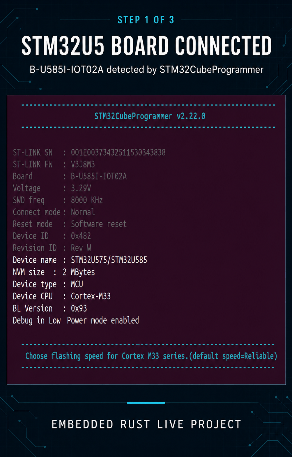
- Part 1: STM32U5 Board Bring-Up and Hardware Verification
- Part 2: Designing the Flash Layout and Boot Process
- Part 3: Developing the STM32 Bootloader in C
- Part 4: Building and Launching Rust Application Firmware
- Part 5: Reading the Onboard Sensors in Rust
- Part 6: Connecting the STM32U5 to Wi-Fi and MQTT
- Part 7: Publishing STM32 Sensor Data to AWS IoT Core
- Part 8: Building the Cloud-Connected Sensor Dashboard
- Part 9: End-to-End Integration, Reconnection and Testing
- Part 10: Final Demonstration and Lessons Learned
Project Current Status
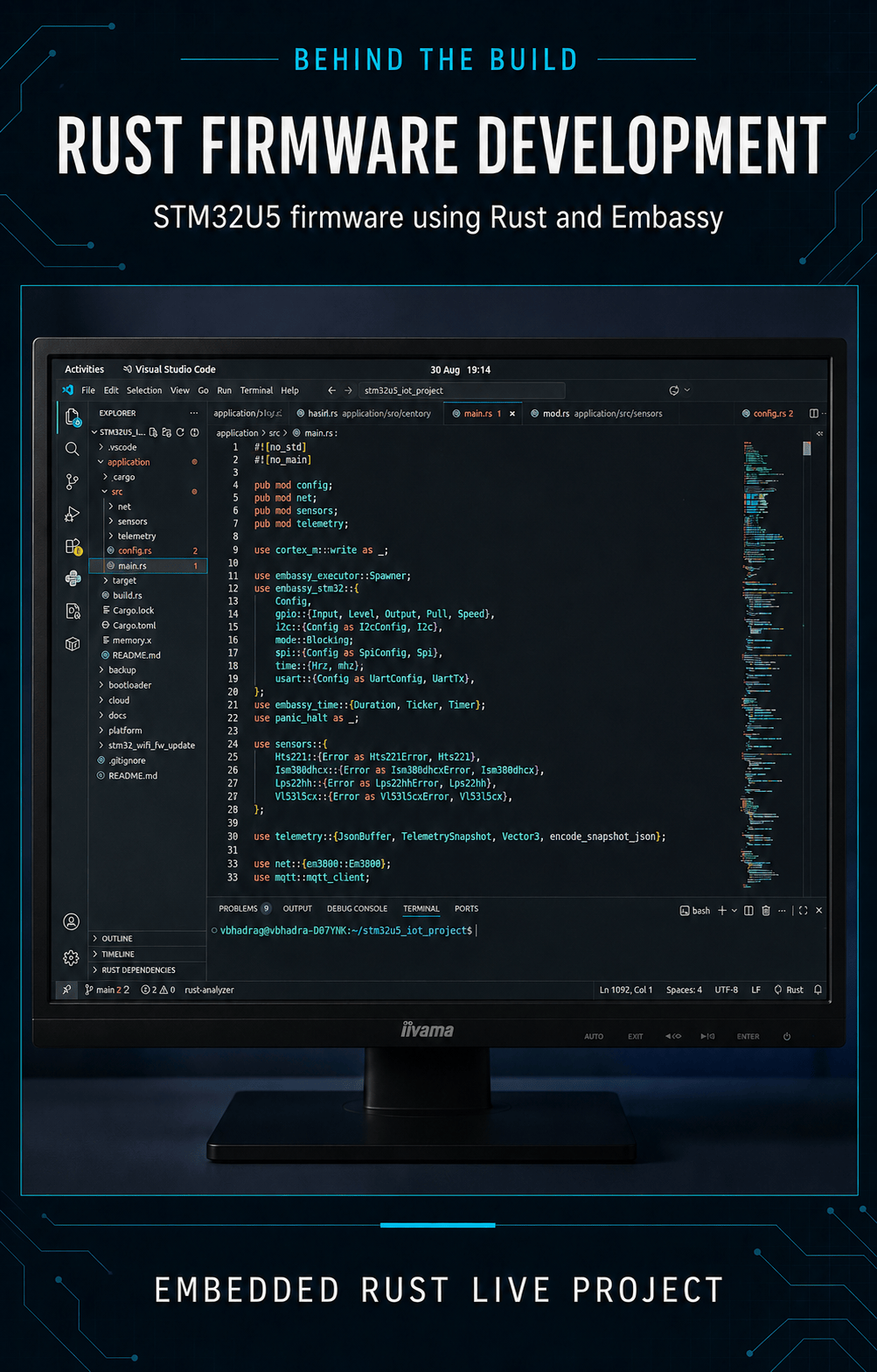
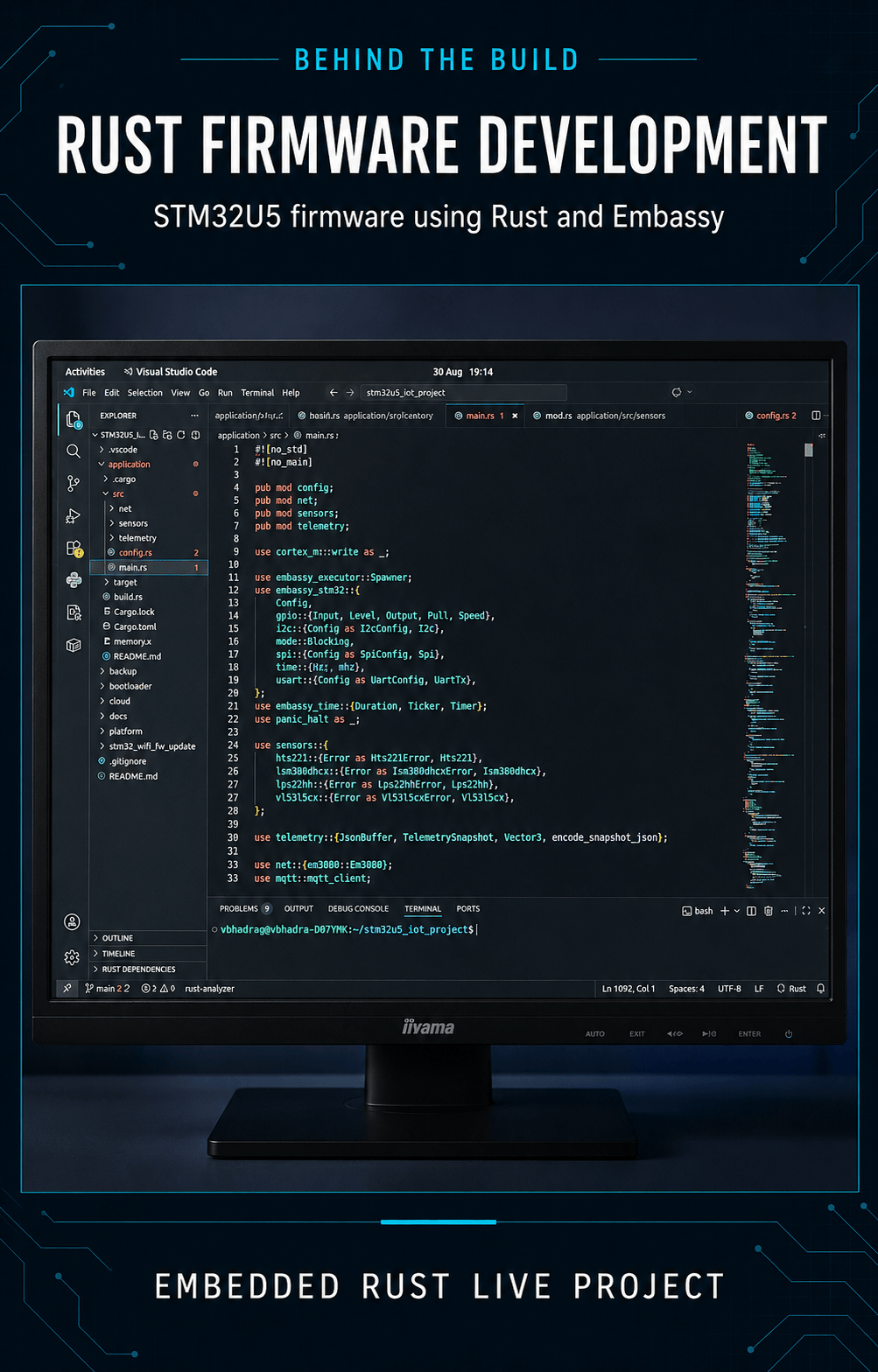
The Rust firmware running on the STMicroelectronics B-U585I-IOT02A development board is now capturing temperature, humidity, atmospheric pressure, accelerometer and gyroscope data. It encodes each sample as JSON and publishes the telemetry over Wi-Fi using MQTT. An MQTT subscriber running on Ubuntu is receiving the live data continuously.
Getting the Wi-Fi connection working involved a few hiccups. Resolving them required live embedded firmware debugging and updating the firmware on the onboard Wi-Fi module. Then, boom, the MQTT telemetry started flowing!
The current verified data path is:
STM32U5 sensors → Embedded Rust firmware → Wi-Fi/MQTT → Ubuntu MQTT subscriber



Project Source Code
Source code, implementation notes and milestone checkpoints are maintained on GitHub. If you are interested in collaborating, in online training, or in access to the full project package, please get in touch.
Discover more from Tech For Talk
Subscribe to get the latest posts sent to your email.
4 Comments