Recently, I found myself working with a cellular USB dongle on an embedded Linux system. I’ve previously documented my experience integrating an LTE device, the EM7565, into a Raspberry Pi 3, which you can read about here: Integrating LTE Device EM7565 into Raspberry Pi 3.
While working with a SORACOM USB dongle to establish a data connection on a Linux system, I encountered some hurdles. Although the SORACOM website offers detailed instructions for desktop Ubuntu/Debian systems, adapting these steps for an Embedded Linux environment proved to be less straightforward. Navigating through a few additional steps that weren’t explicitly covered became necessary. Recognizing the potential value in sharing this information, I’ve decided to document my process in a blog post for the benefit of others who may face similar challenges in the future. Here, I outline the steps you can follow to achieve the same on your system.
Detecting the dongle
To start with monitor the /var/log/message as below:
tail -f /var/log/messagesBut with the existing kernel log level I cannot see much coming up in the logs. So I increase the log level as below:
dmesg -n 8And then I can see there are lot more kernel logs coming up in the /var/log/messages:
[ 1627.795729] musb-hdrc musb-hdrc.1: VBUS_ERROR in a_wait_bcon (89, <AValid), retry #1, port1 00000104
[ 1642.342380] usb 1-1: new high-speed USB device number 3 using musb-hdrc
[ 1642.542287] usb 1-1: New USB device found, idVendor=2c7c, idProduct=0125, bcdDevice= 3.18
[ 1642.551522] usb 1-1: New USB device strings: Mfr=1, Product=2, SerialNumber=0
[ 1642.559342] usb 1-1: Product: EG25-G
[ 1642.563326] usb 1-1: Manufacturer: Quectel
[ 1642.646232] option 1-1:1.0: GSM modem (1-port) converter detected
[ 1642.702602] usb 1-1: GSM modem (1-port) converter now attached to ttyUSB0
[ 1642.711362] option 1-1:1.1: GSM modem (1-port) converter detected
[ 1642.762607] usb 1-1: GSM modem (1-port) converter now attached to ttyUSB1
[ 1642.771408] option 1-1:1.2: GSM modem (1-port) converter detected
[ 1642.821257] usb 1-1: GSM modem (1-port) converter now attached to ttyUSB2
[ 1642.830225] option 1-1:1.3: GSM modem (1-port) converter detected
[ 1642.887592] usb 1-1: GSM modem (1-port) converter now attached to ttyUSB3
[ 1642.943407] qmi_wwan 1-1:1.4: cdc-wdm0: USB WDM device
[ 1642.957111] qmi_wwan 1-1:1.4 wwan0: register 'qmi_wwan' at usb-musb-hdrc.1-1, WWAN/QMI device, 0e:ef:98:75:c0:22
The first important bits to notice in the above log messages are the the below:
[ 1642.542287] usb 1-1: New USB device found, idVendor=2c7c, idProduct=0125, bcdDevice= 3.18
[ 1642.551522] usb 1-1: New USB device strings: Mfr=1, Product=2, SerialNumber=0
[ 1642.559342] usb 1-1: Product: EG25-G
[ 1642.563326] usb 1-1: Manufacturer: Quectel
The kernel USB driver has successfully detected the dongle with vendor ID 2c7c and product ID 0125. Further details reveal that the manufacturer is Quectel, and the product model is EG25-G. This is a positive indication, as our Linux kernel has gathered crucial information about the attached device.
Dongle Drivers
Also, notice the specific driver which is driving this device is qmi_wwan and it had created a device node called cdc-wdm0 under /dev. Check the device under /dev as below:
ls -la /dev/cdc-wdm0
crw-------    1 root     root      180, 176 Mar 14 09:39 /dev/cdc-wdm0
I would also like you to notice the differences in kernel module list before and after the insertion of the USB dongle. I have listed those here: before and after.
The difference is the below listed kernel modules which were inserted by the linux system as soon as the USB dongle was inserted:
simcom_qmi_wwan        28672  0
cdc_wdm                24576  1 simcom_qmi_wwan
usbnet                 45056  1 simcom_qmi_wwan
mii                    16384  1 usbnet
techship_serial        40960  0
Now, the simcom_qmi_wwan module, or possibly just qmi_wwan in your configuration, is a custom vendor-provided QMI_WWAN module. Additionally, usbnet serves as the primary kernel USB infrastructure module. Furthermore, techship_serial, another vendor-specific kernel module, enumerates the serial port. Depending on your Linux system, it might appear under a different name. In my case, it functions properly, so I won’t delve deeper into it in this post. The key point here is to ensure that these or similar kernel modules are being loaded (via insmod/modprobe) by the kernel as soon as you insert the USB dongle.
Serial port enumeration
Also, notice that the following tty device nodes have been created by the driver after the dongle has been attached:
ls -la /dev/ttyUSB*
crw-rw----    1 root     dialout   188,   0 Mar 14 09:49 /dev/ttyUSB0
crw-rw----    1 root     dialout   188,   1 Mar 14 09:49 /dev/ttyUSB1
crw-rw----    1 root     dialout   188,   2 Mar 14 09:49 /dev/ttyUSB2
crw-rw----    1 root     dialout   188,   3 Mar 14 09:49 /dev/ttyUSB3
If you detach the dongle you are likely to see the following kernel messages:
[ 3050.914800] usb 1-1: USB disconnect, device number 2
[ 3050.963010] option1 ttyUSB0: GSM modem (1-port) converter now disconnected from ttyUSB0
[ 3050.972170] option 1-1:1.0: device disconnected
[ 3051.004959] option1 ttyUSB1: GSM modem (1-port) converter now disconnected from ttyUSB1
[ 3051.014074] option 1-1:1.1: device disconnected
[ 3051.074136] option1 ttyUSB2: GSM modem (1-port) converter now disconnected from ttyUSB2
[ 3051.083158] option 1-1:1.2: device disconnected
[ 3051.161429] option1 ttyUSB3: GSM modem (1-port) converter now disconnected from ttyUSB3
[ 3051.170474] option 1-1:1.3: device disconnected
[ 3051.178567] qmi_wwan 1-1:1.4 wwan0: unregister 'qmi_wwan' usb-musb-hdrc.1-1, WWAN/QMI device
And you won’t find these device nodes under /dev anymore:
ls -la /dev/ttyUSB*
ls: /dev/ttyUSB*: No such file or directory
I’m detailing these steps to ensure a clear understanding of the step-by-step process and debugging techniques involved in integrating a USB dongle into Linux. While specific steps may vary slightly for other manufacturers, the overall technique remains largely consistent. This comprehensive approach should provide valuable insights for troubleshooting and adapting to different USB dongles.
Now, from the SORACOM web-page (here) which I mentioned earlier I know that the ttyUSB2 is the port for the serial communication with the device. This may vary if you have other usb devices in the system. In that case you need to figure out which is the serial port to talk to the modem by trial and error. This is the port we can use to issue AT commands to configure the modem. I am not going to elaborate AT commands in this post. But if you are interested you can issue AT commands to the device following the next section.
Issuing AT commands
As explained earlier, to issue AT commands you need to first figure out which serial port is allocated for that. In case of SORACOM the port is ttyUSB2 which is specified in the SORACOM web site. For any other manufacturer you may need to dig out the information from the manufacturer documentation or trial and error. To do trial and error I usually try writing into any ttyUSB* port and see if it responds. Like in this case if I try writing into the ttyUSB0 or ttyUSB1 I won’t get any response back from the device.
# echo -e 'AT+CFUN?\r\n' > /dev/ttyUSB0 | cat < /dev/ttyUSB0As you can see using ttyUSB0 I am not getting any response from the device. Let’s try one more port ttyUSB1 as below:
# echo -e 'AT+CFUN?\r\n' > /dev/ttyUSB1 | cat < /dev/ttyUSB1
Again no response. Lets try ttyUSB2 now:
# echo -e 'AT+CFUN?\r\n' > /dev/ttyUSB2 | cat < /dev/ttyUSB2
AT+CFUN?
+CFUN: 1
OK
As you can see when I wrote to the port ttyUSB2 the device responded back with and answer. The AT command in this case is CFUN. For Quectel (SORACOM uses Quectel chipset) AT commands you may look at this site. CFUN in this case is an AT command to to “Set UE Functionality”. As we can see the CFUN is set to 1 which means the device is set to “Full functionality”. If it is not set you can set it issuing the following command:
# echo -e 'AT+CFUN=1\r\n' > /dev/ttyUSB2 | cat < /dev/ttyUSB2
AT+CFUN=1
OK
Configuring the modem with AT command
Before we can start working with the modem it needs to be configured with the help of AT commands. For the SORACOM (Quectel) modem I had to use the following AT commands to configure it:
Network Registration Status
echo -e "AT+CREG=1\r\n" > /dev/ttyUSB2 | cat < /dev/ttyUSB2
AT+CREG=1
OK
CREG=1 is to Enable network registration.
Define PDP Context
# echo -e "AT+CGDCONT=1, "IP", "super"\r\n" > /dev/ttyUSB2 | cat < /dev/ttyUSB2Once you set the PDP context you can check it with the following command:
# echo -e "AT+CGDCONT?\r\n" > /dev/ttyUSB2 | cat < /dev/ttyUSB2
AT+CGDCONT?
+CGDCONT: 1,"IP","super","0.0.0.0",0,0,0,0
+CGDCONT: 2,"IPV4V6","ims","0.0.0.0.0.0.0.0.0.0.0.0.0.0.0.0",0,0,0,0
+CGDCONT: 3,"IPV4V6","SOS","0.0.0.0.0.0.0.0.0.0.0.0.0.0.0.0",0,0,0,1
OK
Notice the “IP” refers to IP mode and the “super” refers to the corresponding APN.
Operator Selection
# echo -e "AT+COPS=0\r\n" > /dev/ttyUSB2 | cat < /dev/ttyUSB2
AT+COPS=0
OK
Check the selected operator with the below AT command:
# echo -e "AT+COPS?\r\n" > /dev/ttyUSB2 | cat < /dev/ttyUSB2
AT+COPS?
+COPS: 0,0,"O2 - UK Twilio",7
Once the above is all set we need to now configure our wwan driver.
Configuring the Driver
Next, after some trial and error, I decided to consult the SORACOM link to gain a better understanding of the next steps. This link provides a setup script (setup_eg25.sh) that helped me discern the direction to proceed. While I won’t strictly adhere to every detail outlined on this web-page, it may still be beneficial for you to review. Moving forward, we’ll proceed with the following steps:
Setting ip raw mode
We will put the driver in ip raw mode and for that we need to first bring down the interface wwan0. Now where did I get the wwan0 interface reference? Please look back at your kernel messages which appeared just after attaching the dongle and try locate the below line:
[ 5216.856401] qmi_wwan 1-1:1.4 wwan0: register 'qmi_wwan' at usb-musb-hdrc.1-1, WWAN/QMI device, e2:99:b7:f3:28:93It is telling you that the qmi_wwan driver had registered a wwan0 interface for you. However, if you check the ifconfig list this interface doesn’t show up at this point:
# ifconfig
can0      Link encap:UNSPEC  HWaddr 00-00-00-00-00-00-00-00-00-00-00-00-00-00-00-00
          UP RUNNING NOARP  MTU:16  Metric:1
          RX packets:0 errors:0 dropped:0 overruns:0 frame:0
          TX packets:0 errors:0 dropped:0 overruns:0 carrier:0
          collisions:0 txqueuelen:10
          RX bytes:0 (0.0 B)  TX bytes:0 (0.0 B)
          Interrupt:49

can1      Link encap:UNSPEC  HWaddr 00-00-00-00-00-00-00-00-00-00-00-00-00-00-00-00
          UP RUNNING NOARP  MTU:16  Metric:1
          RX packets:0 errors:0 dropped:0 overruns:0 frame:0
          TX packets:0 errors:0 dropped:0 overruns:0 carrier:0
          collisions:0 txqueuelen:10
          RX bytes:0 (0.0 B)  TX bytes:0 (0.0 B)
          Interrupt:50

eth0      Link encap:Ethernet  HWaddr 54:45:38:00:C2:D6
          UP BROADCAST MULTICAST  MTU:1500  Metric:1
          RX packets:247 errors:0 dropped:0 overruns:0 frame:0
          TX packets:267 errors:0 dropped:0 overruns:0 carrier:0
          collisions:0 txqueuelen:1000
          RX bytes:49420 (48.2 KiB)  TX bytes:38760 (37.8 KiB)

lo        Link encap:Local Loopback
          inet addr:127.0.0.1  Mask:255.0.0.0
          inet6 addr: ::1/128 Scope:Host
          UP LOOPBACK RUNNING  MTU:65536  Metric:1
          RX packets:72 errors:0 dropped:0 overruns:0 frame:0
          TX packets:72 errors:0 dropped:0 overruns:0 carrier:0
          collisions:0 txqueuelen:1000
          RX bytes:5904 (5.7 KiB)  TX bytes:5904 (5.7 KiB)
Now, lets set this interface to raw ip mode as below:
# ifconfig wwan0 down
# echo "Y" > /sys/class/net/wwan0/qmi/raw_ip
[ 5500.755096] qmi_wwan 1-1:1.4 wwan0: mode: raw IP
# cat /sys/class/net/wwan0/qmi/raw_ip
Y
# ifconfig wwan0 up
[ 5518.332654] qmi_wwan 1-1:1.4: qmi_wwan_manage_power() pmcount=1, on=1
Please note you may not see the some of the above kernel messages unless you enable kernel Dynamic debug.
Kernel Dynamic Debug
Kernel dynamic debug functionality is enabled through the CONFIG_DYNAMIC_DEBUG configuration option in the kernel. To activate it, you can either use “make menuconfig” or manually add this option to your defconfig file. While I won’t delve into the specifics of these steps here, it’s worth noting that in my kernel configuration, dynamic debug is enabled. To access additional logs, I follow these steps:
mount -t debugfs none /sys/kernel/debug
echo -n 'file techship_serial.c +p' > /sys/kernel/debug/dynamic_debug/control
echo -n 'file qmi_wwan.c +p' > /sys/kernel/debug/dynamic_debug/control
echo -n 'file qcserial.c +p' > /sys/kernel/debug/dynamic_debug/control
echo -n 'file option.c +p' > /sys/kernel/debug/dynamic_debug/control
echo -n 'file simcom_qmi_wwan.c +p' > /sys/kernel/debug/dynamic_debug/control
echo -n 'file techship_qmi_wwan.c +p' > /sys/kernel/debug/dynamic_debug/control
echo -n 'file techship_serial.c +p' > /sys/kernel/debug/dynamic_debug/control
echo -n 'file qcserial.c +p' > /sys/kernel/debug/dynamic_debug/control
For the SORACOM (Quectel) device, the configuration provided should suffice, though you may need to add or remove files based on your specific requirements or the device you’re working with. With the wwan0 interface set to raw IP mode, the next step is to bring the network up. However, it’s worth noting that although you’ve executed ‘ifconfig wwan0 up,’ the wwan0 interface might appear in ifconfig but isn’t properly configured yet. Consequently, you won’t have internet access at this stage. Additionally, observe that the wwan0 interface lacks an associated IP address.
Starting the network
Before delving into the network setup process, let’s experiment with obtaining an IP address for the wwan0 interface using udhcp:
# udhcpc wwan0
udhcpc: started, v1.33.0
udhcpc: sending discover
udhcpc: sending discover
udhcpc: sending discover
As you can see the device is not getting an IP address. I then tried setting the APN for the device. I am using a SIM from the provided Twilio and it is a super SIM. For the super SIM from Twilio the APN is “super”. But then I took a different route to activate the wwan0 interface rather than trying to work with AT commands. But if you care interested you may consult this page in the Twilio website.
Monitoring using tcpdum
You can monitor what’s going on at this point using tools like tcpdum. To run tcpdum you need to enable the package in the linux config. You can do it by navigating in the make menuconfig -> Target Package -> Network Application -> tcpdump. Once you have tcpdump in your linux box, connect your linux box to the same network as your laptop/PC (yes, you have to be able to have some sort of connectivity in the box so that you can have a separate console to run tcpdum), ssh into the box as below:
$ ssh  root@10.42.0.154
root@10.42.0.154's password: xxxxxx
Once you are logged in into the box run tcpdum with the following command:
# tcpdump -G 60 -W 1 -w /var/log/capture.pcap -i wwan0-G to specify how long (in sec) you want the capture for
-W represents the number of iterations you want for the capture to happen
– w specifies the logfile where the capture should be stored
-i represents the interface for which you want the capture
Now on the linux serial port I am running the udhcp command as follows:
# udhcpc -q -f -i wwan0
udhcpc: started, v1.33.0
udhcpc: sending discover
udhcpc: sending discover
udhcpc: sending discover
udhcpc: sending discover
udhcpc: sending discover
On the ssh portal I am running the tcpdump. After 60 sec tcpdump utility will return and the packet exchange will be captured in the log file /var/log/capture.pcap. When the tcpdump utility returns you should be able to see something like the below:
# tcpdump -G 60 -W 1 -w /var/log/capture.pcap -i wwan0
tcpdump: listening on wwan0, link-type RAW (Raw IP), snapshot length 262144 bytes
Maximum file limit reached: 1
7 packets captured
7 packets received by filter
0 packets dropped by kernel
As you can see 7 packets have been captured in 60 seconds. Now time to check what has been captured by the tcpdump.
Transfer the /var/log/capture.pcap file to the local host PC/laptop. I am assuming you are still connected to the box via the ssh. To transfer the file from the linux box to the PC I use scp command as below:
Host Laptop (Ubuntu)
$ scp root@10.42.0.154:/var/log/capture.pcap .
root@10.42.0.154's password:
capture.pcap
To observe the tcpdump file *.pcp you would need to install wireshark. Once you have installed wireshark, launch it and open the pcap file. I usually lauch the wireshark from the linux (host laptop) command prompt like below:
$ wireshark Go to File and Open the capture.pcap in Wireshark. To filter the dhcp messages you can use the filter bootp in the filter pane. However in this case as there are only 7 packets which have been captured you don’t need to bother too much about filtering. How if you notice in the wireshark the following dhcp packets have been captured:
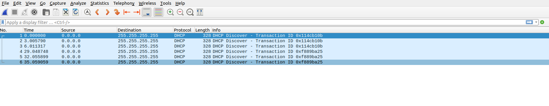
As you can see only DHCP Discover have been sent form the Linux box and there is no response to it. Ideally, there should be offer in response to Discover from any available DHCP server. But seems like it didn’t find any DHCP server. That explains why there is no IP assigned to the Linux box yet. In the next step we will look into qmicli tool and try to start the network.
Installing qmicli package
I found it is much easier to work with the qmicli package and setup the network than trying to use the AT commands for this particular dongle from SORACOM/Quectel. To install the qmicli package you can use the make menuconfig and follow the following config screen to get it into your buildroot build (I am using Buildroot). So please follow the following screen if you wish to get the qmicli package:
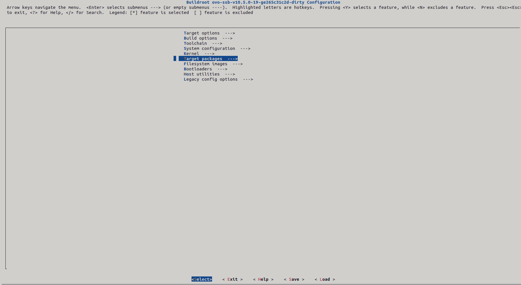
Go to Target Packages as show above and then inside the Target Packages go to Libraries as shown below:
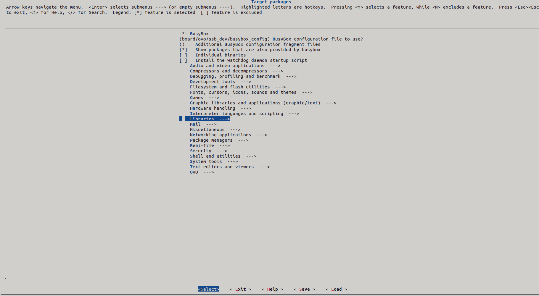
Inside Libraries go to the menu option Hardware Handling as shown below:
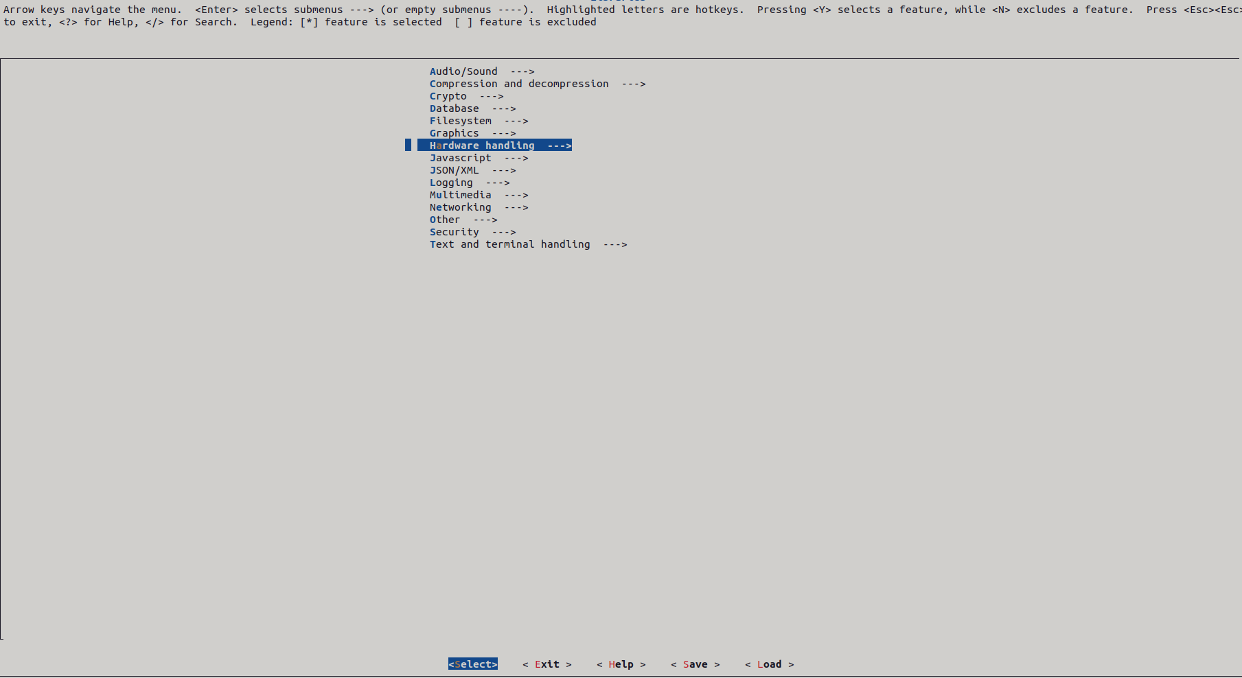
Inside Hardware Handling you should see the libqmi library as listed below:
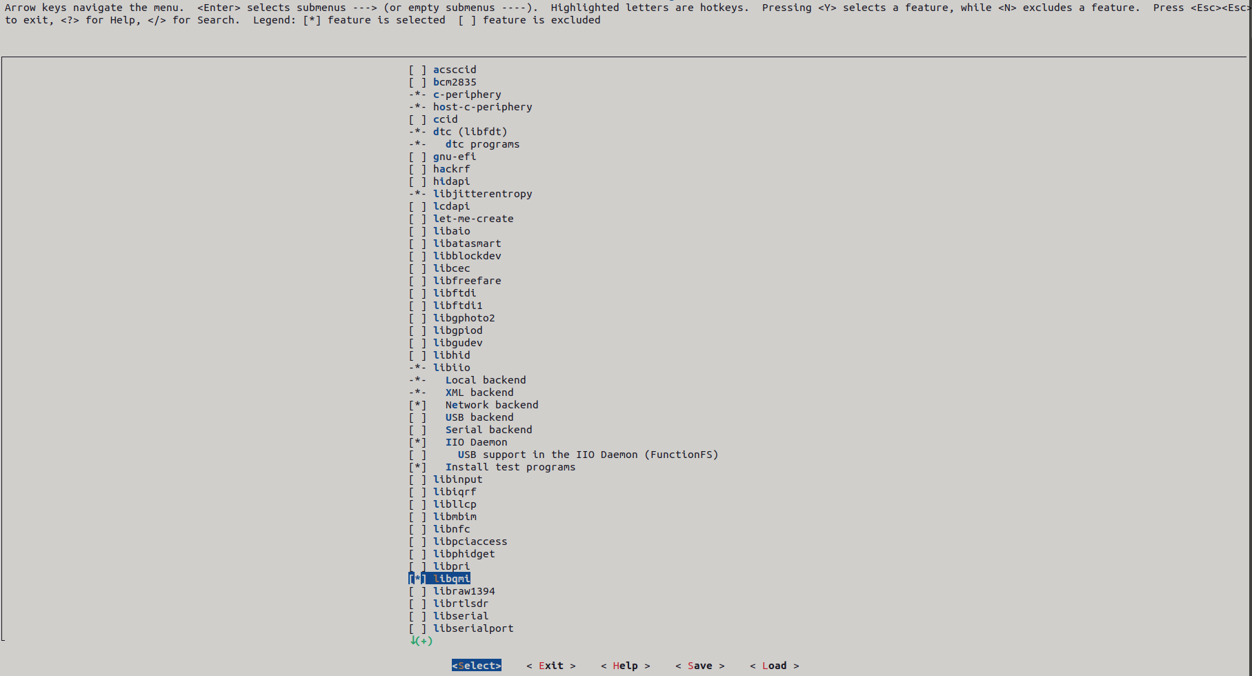
Press the space bar to select the option, and continue pressing “Exit” until you reach the last screen where it asks to save the new configuration. After saving, run “make” and the qmicli package should be available in your running system. Another method of adding this package is by including BR2_PACKAGE_LIBQMI in your defconfig file and setting it to ‘y’ as shown below:
BR2_PACKAGE_LIBQMI=yRegardless of the method chosen, ensure that the qmicli package is present on your Linux system. If it’s not already installed, you’ll need to add it. Once available, issue the following command to bring up the network:
qmicli -d /dev/cdc-wdm0 --device-open-net="net-raw-ip|net-no-qos-header" --wds-start-network="super" --client-no-release-cidPlease note that in this example, “super” represents the actual Access Point Name (APN) for the Twilio service provider. If you’re using a different provider, you’ll need to determine their APN name and set it accordingly in the configuration.
Once you do the above command you should see the following messages on the console:
[/dev/cdc-wdm0] Network started
        Packet data handle: '2268731424'
[/dev/cdc-wdm[ 8365.272699] qmi_wwan 1-1:1.4: qmi_wwan_manage_power() pmcount=3, on=0
0] Client ID not released:
        Service: 'wds'
            CID: '17'
As it says the network has started. The important things to note here are the handle id (2268731424) and the CID (17) because you may need it to stop the network.
Acquiring the IP
Once the network has started, we need to acquire and IP for the interface wwan0. To do that do the following:
# udhcpc -q -f -i wwan0
^[Okudhcpc: started, v1.33.0
udhcpc: sending discover
udhcpc: sending select for 100.80.123.230
udhcpc: lease of 100.80.123.230 obtained, lease time 7200
deleting routers
adding dns 8.8.4.4
adding dns 8.8.8.8
As illustrated, the device has successfully obtained an IP address from the service provider. It’s essential to ensure that your device isn’t connected to any other network via Ethernet or Wi-Fi. Otherwise, there’s a risk that it may acquire an IP address from a different DHCP server instead of the intended service provider which is Twilio in this case.
Checking the internet connection
To check the connection you can ping the google public server (8.8.8.8) as below:
# ping -I wwan0 8.8.8.8
PING 8.8.8.8 (8.8.8.8): 56 data bytes
64 bytes from 8.8.8.8: seq=0 ttl=115 time=280.336 ms
64 bytes from 8.8.8.8: seq=1 ttl=115 time=237.170 ms
64 bytes from 8.8.8.8: seq=2 ttl=115 time=235.666 ms
64 bytes from 8.8.8.8: seq=3 ttl=115 time=235.040 ms
64 bytes from 8.8.8.8: seq=4 ttl=115 time=234.658 ms
64 bytes from 8.8.8.8: seq=5 ttl=115 time=233.220 ms
You can once again capture DHCP messages using tcpdump, filtering the messages with the bootp filter to observe the DHCP exchange, as demonstrated below:
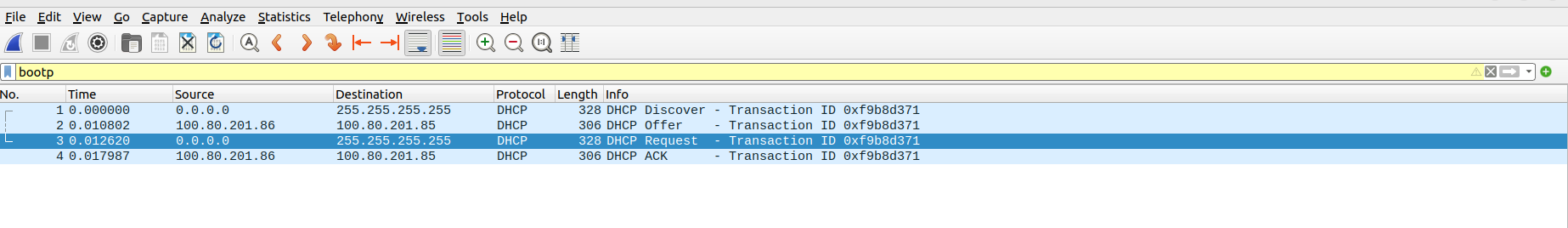
Now, you can observe that the remote DHCP server has responded with a message type “Offer,” providing an IP address (10.80.201.85). Upon receiving the offered IP, the Linux box responds by accepting it in a DHCP Request message. Finally, the remote DHCP server acknowledges this by sending back a DHCP ACK message.
Automating using bash script
So far, we’ve been manually performing each step, from setting up the interface to starting the network, acquiring the IP, and verifying connectivity with a ping. However, having to repeat these steps manually every time we detach and reattach the dongle is not ideal. We can streamline this process by using a script. Below is a script I’ve written to automate all of these tasks in one go:
#!/bin/bash
# Sending lsusb output onto variable
readarray -t usbinterfaces <<< "$(lsusb)"

# Declaring the interfaces product ID's
SORACOM_ONYX_DONGLE="2c7c:0125" #eth1 not yet actiavted
# Seeing if the interface connected is the LTE Alcatel dongle
if [[ "${usbinterfaces[*]}" =~ ${SORACOM_ONYX_DONGLE} ]]; then
  NOW=$(date '+%d/%m/%Y %H:%M:%S')
  echo "$NOW"" - ""$SORACOM_ONYX_DONGLE" "Soracom Onyx dongle" >> /var/log/dongle.log
  ifconfig wwan0 down
  echo "Y" > /sys/class/net/wwan0/qmi/raw_ip
  ifconfig wwan0 up
  qmicli -d /dev/cdc-wdm0 --device-open-net="net-raw-ip|net-no-qos-header" --wds-start-network="super" --client-no-release-cid
  udhcpc -q -f -i wwan0
  ping -I wwan0 8.8.8.8
  exit 0
fi
The above script simplifies the process by performing the following actions:
- Utilizes the
lsusbcommand to gather information about connected USB devices, including the vendor ID and product ID pair for all dongles, including SORACOM. - Checks if the vendor ID and product ID pair for the SORACOM dongle is present in the output from
lsusb. - If the pair is found, it confirms that the dongle is attached. Once confirmed, the script automates the steps outlined in previous sections of this blog post.
With the script in place, we’ve automated some of our manual labor. However, there will still be some manual intervention required to launch the script every time we detach and reattach the dongle. To address this, we can utilize udev rules.
Automating dongle activation using udev rules
Udev rules allow us to define specific actions to be performed when certain events, such as attaching or detaching a device, occur in the system. By creating a udev rule for our USB dongle, we can trigger the execution of our script automatically whenever the dongle is attached.
Here’s how we can set up a udev rule to achieve this:
- Identify the vendor ID and product ID of your SORACOM dongle using
lsusb. - Create a new udev rule file in
/etc/udev/rules.d/, for example,99-soracom-dongle.rules. - In this rule file, define a rule that matches your SORACOM dongle based on its vendor ID and product ID.
- Specify the action to be taken when the dongle is attached, such as executing your script.
Here’s an example of what the udev rule might look like:
# 99-soracom-dongle.rules
ACTION=="add", SUBSYSTEM=="usb", ATTRS{idVendor}=="<your_vendor_id>", ATTRS{idProduct}=="<your_product_id>", RUN+="/path/to/your/script.sh"
Replace <your_vendor_id> and <your_product_id> with the actual vendor ID and product ID of your SORACOM dongle, and /path/to/your/script.sh with the path to your script.
One of the primary locations to search for udev rules is /etc/udev/rules.d/. Browsing this directory typically reveals a collection of pre-existing udev rules. To streamline the process, I’ll utilize an existing rule file rather than creating a new one. For simplicity, I’ve selected the file /etc/udev/rules.d/70-persistent-net.rules for this purpose. While you have the option to create a new rule file, I’m opting to append my udev rule to this existing file to maintain simplicity. Within this file, I’ll insert a new rule tailored to my SORACOM device. The rule I’m adding is as follows:
SUBSYSTEM=="net", ACTION=="add", ATTRS{idVendor}=="2c7c", ATTRS{idProduct}=="0125", ATTR{type}=="1", RUN+="/opt/ovo/dongle_connection_bg.sh"Now, whenever you attach your SORACOM device, udev will automatically trigger the execution of your script, simplifying the process and eliminating the need for manual intervention.
Twilio Dashboard
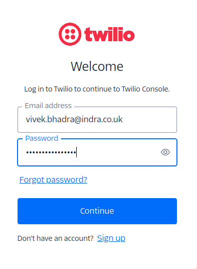
Finally you can register in Twilio to observe your data usage. You need to register yourself before you do that. Once you have registered and logged in go to the following options in the dashboard:

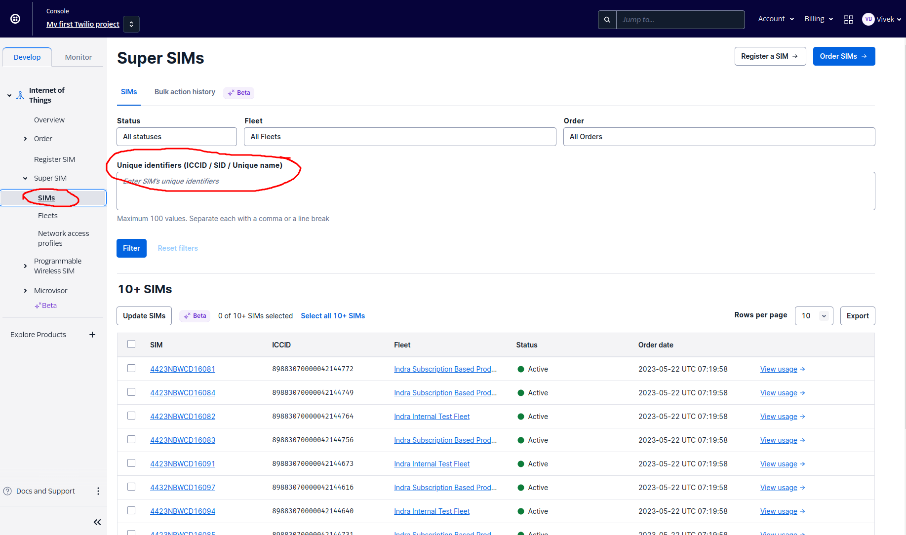
In the above ICCID identifier you can stick in your SIM’s ICCID and see the data usage. By the way if you haven’t registered your SIM yet please do so before you do any of these steps. Ok, to get the ICCID you can issue the following command in the linux box:
echo -e "AT+ICCID\r\n" > /dev/ttyUSB2 | cat < /dev/ttyUSB2
AT+ICCID
+ICCID: 8942310223004188205F
OK
Copy the ICCID of your SIM card which you get form the above AT command and stick it in the ICCID identifier in the Twilio dashboard as below:
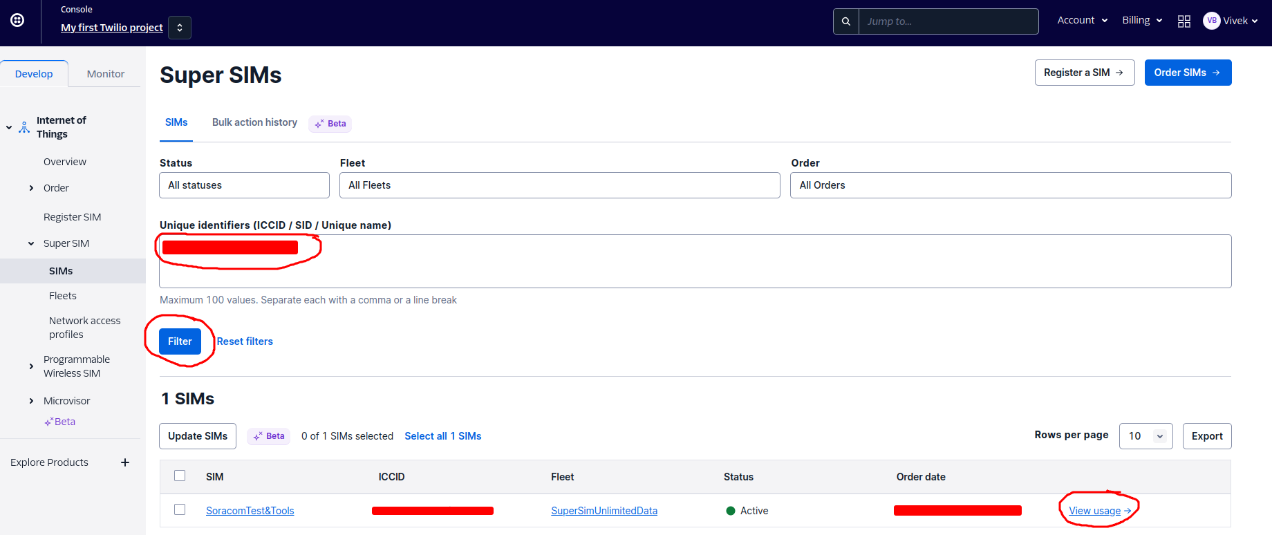
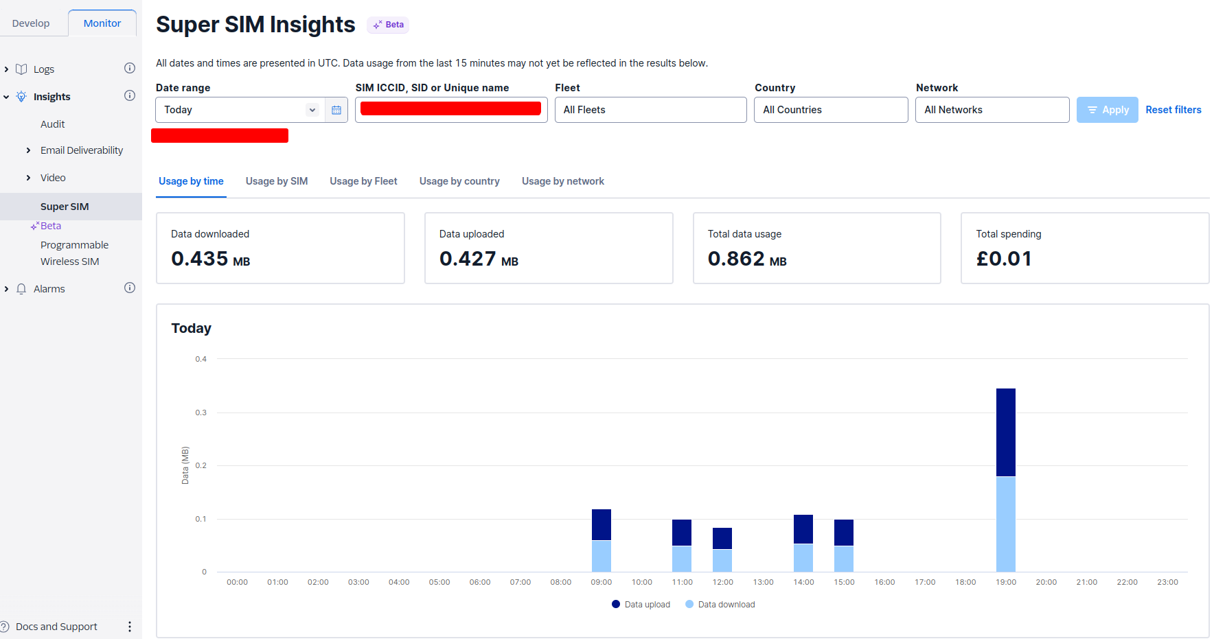
Once you click on the View Usages button as shown in the above picture the data usages of you device should be displayed in the dashboard. You may like to keep pinging the 8.8.8.8 IP and consume some data so that it appears on the dash board. Also in the dashboard you choose the time span you want to display the data for. For example if I filter the data for just today it looks like the below:
So now you are sure you have a data connection established using your SORACOM Onyx dongle. The dongle keeps glowing like this when there is a stable connection:
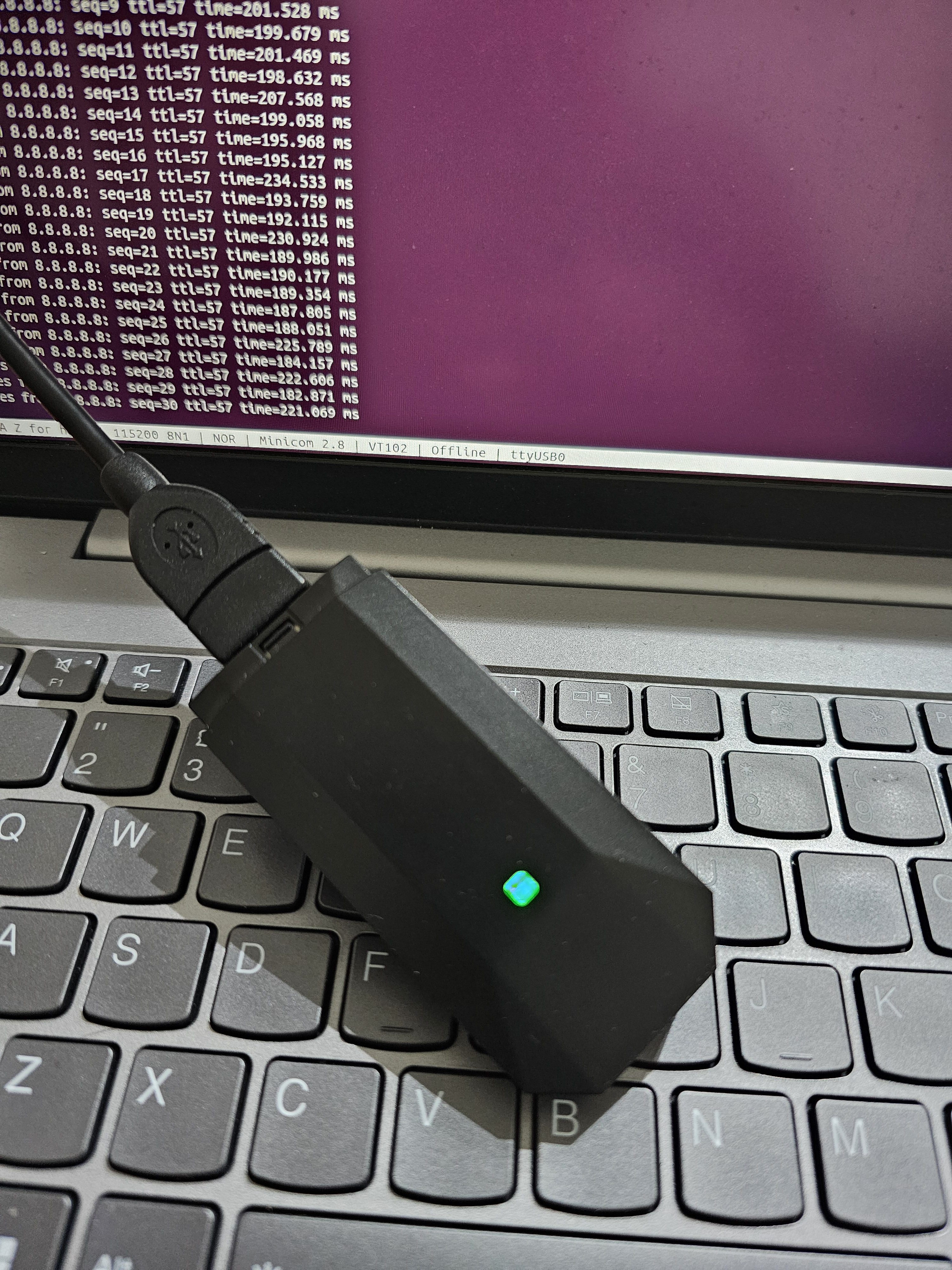
Ok, that’s all for now, see you in the next blog!


Leave a Reply